Please follow and like us:

Scirocco R12 to R134a Retrofit, System Preparation
- For Scirocco R12 to R134a Retrofit, review all Cautions, Warnings and A/C refrigerant system safety measures stated in appropriate model repair information:
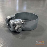
–> Repair Manual, Air Conditioning, Repair Group 87. - Always use Underwriter’s Laboratory (UL) approved refrigerant service equipment such as Kent Moore ACR3, ACR4 or equivalent.
- Before proceeding with retrofit, perform a visual inspection and functional test of complete A/C system; including instrument panel outlet temperature, air distribution, refrigerant system components, system pressure and leak test:
–> Repair Manual, Air Conditioning, Repair Group 87. Repair/replace parts as necessary. - Always refer to the most recent parts information for affected models when replacing damaged or defective R-12 refrigerant system parts (including the routine replacement of O-rings).
- If replacement of damaged or leaking refrigerant hoses, compressors, evaporators and condensers is necessary, blow compressed air (followed by nitrogen) through all remaining. Also, disconnected, free flowing system components before assembly in order to remove moisture, impurities and remaining refrigerant oil.
- If a component is replaced prior to retrofitting the system to R-134a, an appropriate amount of PAG refrigerant oil must be added. Additionally, for oil quantities per component, refer to Oil Distribution charts.
- Replacement compressors are factory filled with R-12 compatible compressor oil. For example, if compressor replacement is necessary, the factory filled compressor oil must be drained and replaced with appropriate quantity of PAG refrigerant oil;
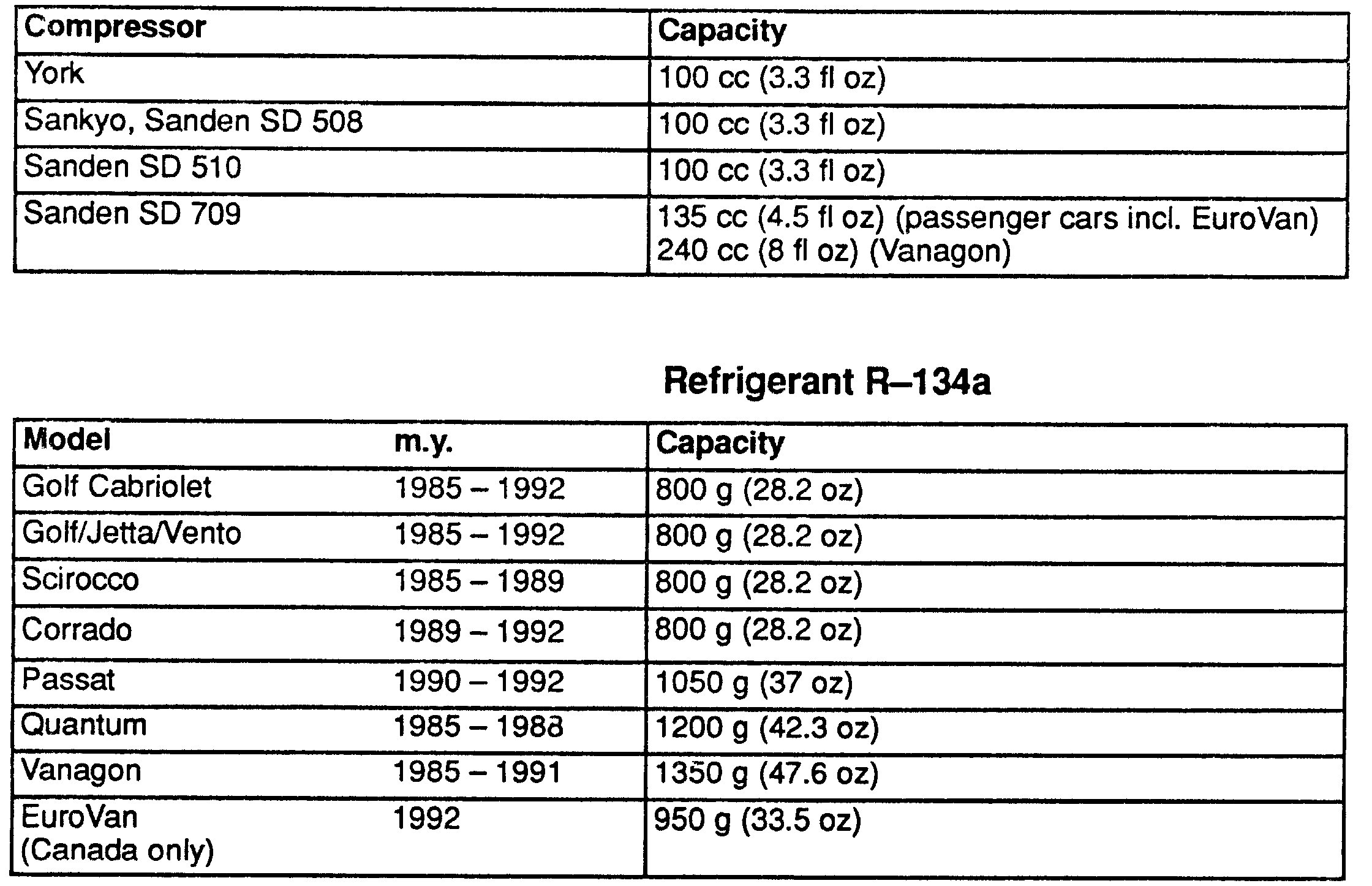
Identify compressor type and fill according to table.
Parts Requirements
All models require the following parts:
- Adapter Kit: Part No. 357 820 794 / 357820794
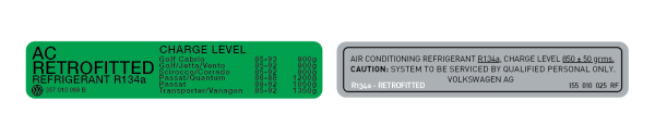
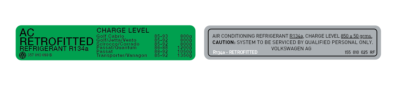
- Labels:
- PAG refrigerant oil: Part No. G 052 154 A2 / G052154A2
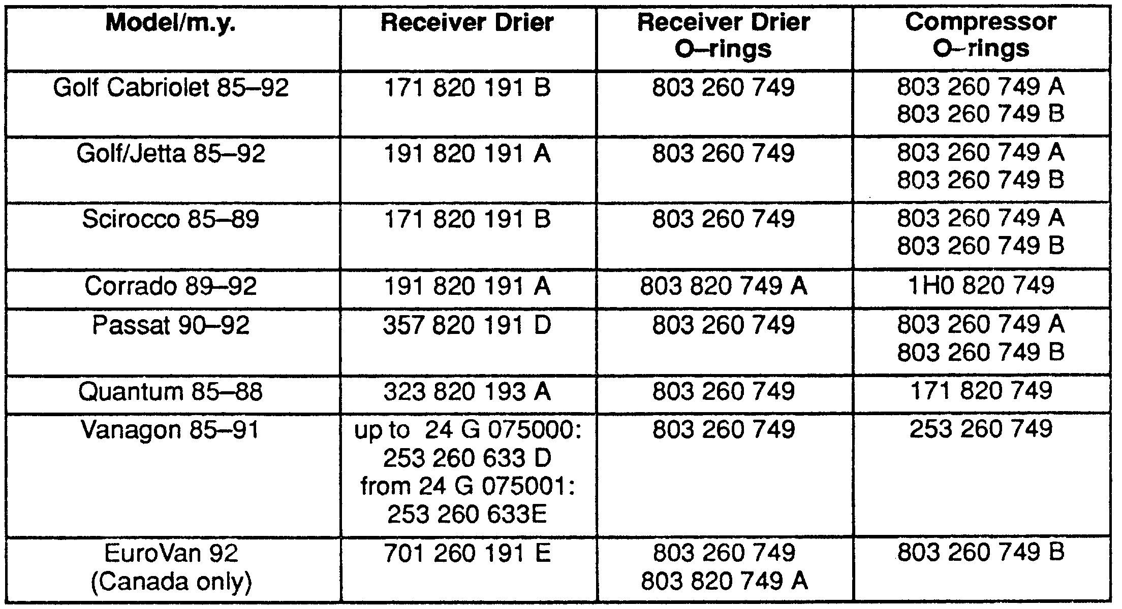
- Receiver drier*
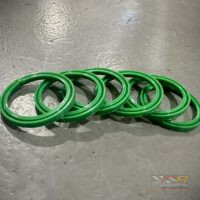
- Receiver drier O-rings*
- Compressor O-ring*
- *Refer to the chart for applicable part numbers.
Caution! Part numbers are for reference only. Always check with your Parts Dept. for the latest parts information.
Retrofit Procedure
- Firstly. discharge and capture refrigerant R-12 using Kent Moore ACR3 or equivalent.
- Secondly, evacuate system to remove any R-12 contaminants
- Next, remove refrigerant oil from compressor; depending on accessibility, use one of the following methods:
- Use refrigerant oil evacuation feature of Kent Moore ACR3, ACR4 or equivalent.
- Remove compressor, unscrew oil drain plug and drain refrigerant oil.
- Fourthly, identify compressor type and fill with quantity of PAG refrigerant oil specified in table.
- Fiftly, reinstall compressor (if removed).
- Next, install new O-rings on compressor suction and discharge hose fittings.
- Then, Replace receiver drier. Use new O-rings
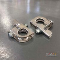
- Next, Identify and install correct R-134a adapters (from Kit Part No.357 820 794) to high pressure and low pressure service valves.
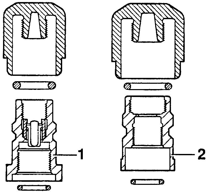
- Low pressure valve -1-, 7/16″ connection Part No. 357 820 797 A / 357820797A
- High pressure valve -2-, 3/8″ connection Part No. 357 820 797 / 357820797 or
High pressure valve -2-, 7/16″ connection Part No. 357 820 797B / 357820797B - Evacuate system for a minimum of 30 minutes using Kent Moore ACR4 or equivalent A/C machine.
- Charge system with refrigerant R-134a, See refrigerant capacity table below.
- Perform A/C system quality check and leak test –> Repair Manual, Air Conditioning, Repair Group 87.
- Lat but not lese, install new R-134a retrofit decal over original R-12 label on radiator support. Click here to order yours
Capacity Tables
PAG Refrigerant Oil – for passenger cars:
-
- Volkswagen:
- 500mL: G 052 154 A2 / G052154A2
- OES / Behr:
- 1.0L: 708 181 76NA / 70818176NA
- 500mL: 708 181 77NA / 70818177NA
- Volkswagen:
R-134a Retrofit, Refrigerant Oil Distribution
- If replacement of defective components is necessary before retrofitting to R-134a, identify refrigerant circuit. To do this, go by compressor type and add PAG refrigerant oil directly to component according to following application charts. Also, read everything on this page and follow the Caution statments.
Caution!
- The following total system oil capacities are the maximum allowed for each compressor and refrigerant circuit combination.
- Furthermore, Please do not exceed the total system oil capacity. Compressor damage and a decrease in cooling performance will result.
York Compressor
| Location | Specification |
|---|---|
| Condenser | 10 cc (0.3 fl oz) |
| Evaporator | 50 cc (1.7 fl oz) |
| Receiver Drier | 20 cc (0.7 fl oz) |
| High Pressure Hose | 15 cc (0.5 fl oz) |
| Low Pressure Hose | 15 cc (0.5 fl oz) |
| Total System Oil Capacity | 300 cc (10.0 fl oz) |
Sanden SD 508 Compressor
| Location | Specification |
|---|---|
| Condenser | 20 cc (0.7 fl oz) |
| Evaporator | 30 cc (1.0 fl oz) |
| Receiver Drier | 20 cc (0.7 fl oz) |
| High Pressure Hose | 10 cc (0.3 fl oz) |
| Low Pressure Hose | 10 cc (0.3 fl oz) |
| Total System Oil Capacity | 175 cc (5.8 fl oz) |
Sanden SDV 710 Compressor
| Location | Specification |
|---|---|
| Condenser | 20 cc (0.7 fl oz) |
| Evaporator | 30 cc (1.0 fl oz) |
| Receiver Drier | 20 cc (0.7 fl oz) |
| High Pressure Hose | 10 cc (0.3 fl oz) |
| Low Pressure Hose | 10 cc (0.3 fl oz) |
| Total System Oil Capacity | 120 cc (4.0 fl oz) |
Sanden SD 709 Compressor (only passenger vehicles)
| Location | Specification |
|---|---|
| Condenser | 15 cc (0.5 fl oz) |
| Evaporator | 20 cc (0.7 fl oz) |
| Receiver Drier | 10 cc (0.3 fl oz) |
| High Pressure Hose | 10 cc (0.3 fl oz) |
| Low Pressure Hose | 10 cc (0.3 fl oz) |
| Total System Oil Capacity | 135 cc (4.5 fl oz) |